|
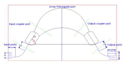
In recent years, Array Waveguide Gratings (AWG) have become increasingly popular as wavelength (de)multiplexers for WDM applications. They have proven to be capable of precise demultiplexing of a large number of channels with relatively low loss. Therefore, AWGs are playing a key role in dense WDM network systems. The main features of AWG multiplexer/demultiplexers are low fiber-to-fiber loss, narrow and accurate channel spacing, large channel number, polarization insensitivity, high stability and reliability, and suitability for mass production. Because the fabrication is based on standardized photolithographic techniques, the integration of the AWG and etching grating offers many advantages such as compactness, reliability, large fabrication tolerances (no vertical deep etching), and significantly reduced fabrication and packaging costs. The inherent advantages of the AWG also include precisely controlled channel spacing (easily set to ITU grid), simple and accurate wavelength stabilization, and uniform insertion loss. All of the above factors make AWG a key optical component in photonic integrated circuits (PIC) of optical WDM communications. AWGs have unique properties such as low insertion loss, large optical bandwidth and output number, compactness (small device dimensions), polarization independence, low cross talk, and excellent fabrication tolerances. As a result, AWGs have many potential applications such as wavelength multiplexers/demultiplexers, add-drop multiplexers, couplers, dividers/splitters, combiners, switches, filters, samplers/monitors and equalizers. They also can be easily fabricated in more complex PICs such as lasers, receivers, modulators, amplifiers and WDM circuits. Note:For the simulation of an AWG device, there are two coupler regions in the device. The lengths are defined by the coupler length and the simulation region (F1, F2, F3 and F4). The mesh numbers from the simulation setting dialog box are only for these regions. Only the field of the second coupler region is available. |
|
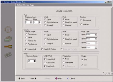 AWG Definition Panel for Pre-defined Shape |
 MxN AWG |
|
APSS provides two simulation methods for AWG: analytical and numerical. The analytical method is a fast way to estimate AWG performance. In this method, all the lines, input/output ports and array lines are considered as a phase shift. Coupling and bending losses are not considered for these lines. Then, using the fast Fourier transform (FFT), a Gaussian beam propagation method is applied in the star coupler section. The calculation of the star coupler section is done only at the center wavelength and is used for the whole wavelength range. To calculate the overall performance of an AWG, the results of different sections (transfer matrixes) are put together using the transfer matrix of each block. The numerical method is an accurate method of analysis; however it is time consuming. In this method, the cylindrical BPM is used for all lines, input/output ports and array lines. Bending loss is considered for all the lines and then BPM is used to analyze the star coupler parts. Coupling between lines is also considered using BPM. |
 1×16 AWG Layout (put actual values in the pre-defined shape) |
 BPM Results at the Second Star Coupler |
| The following spectrum is obtained because the focusing position is determined by wavelength. |
 Spectrum at 16 Output Ports |